Astatic Microphones
Schematics & Wiring Diagrams
D-104 Basic Amplifier; Some use 2N2712
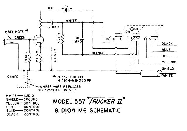
557 Trucker II & D104M6
TMD-107 Relay

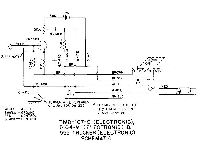
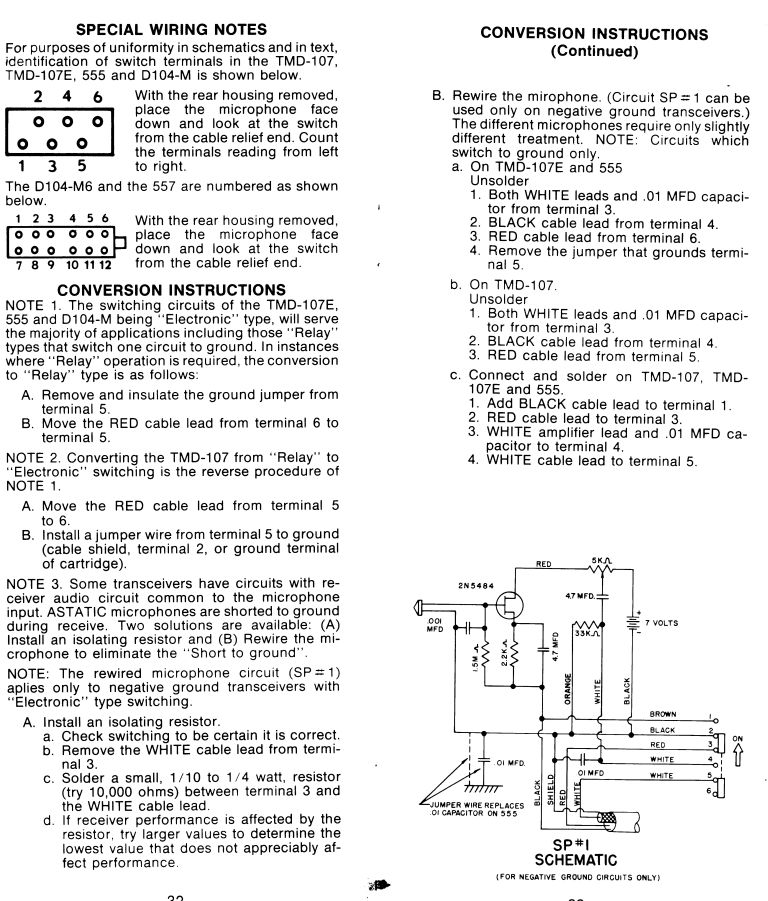
TMD-107-Em D-104M & 555 Trucker - All with electronic switching
Electronic / Relay switchng conversions
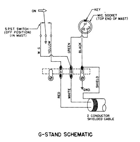
G-Stand
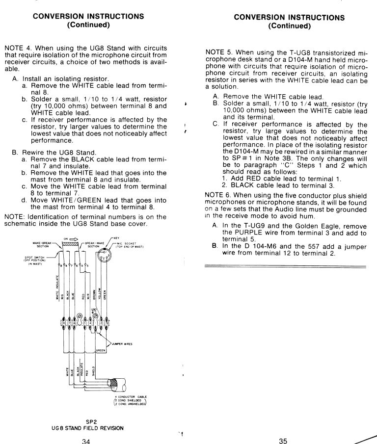
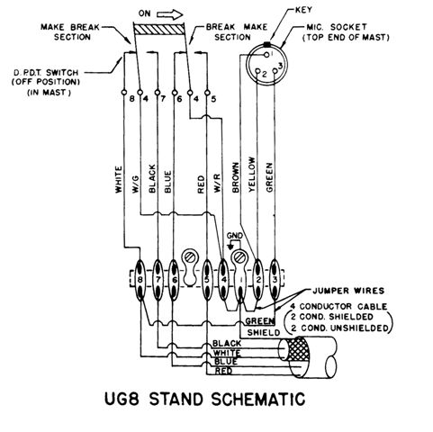
UG8-Stand
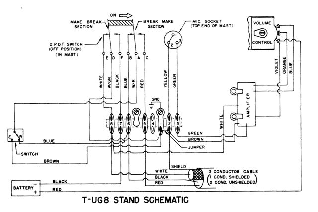
T-UG8 Stand
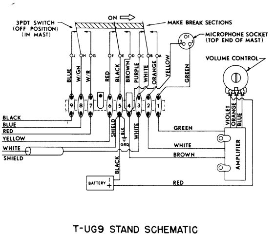
T-UG9 Stand
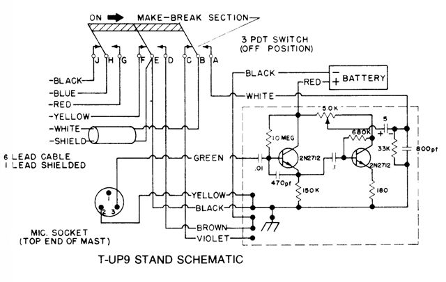
T-UP9 Stand
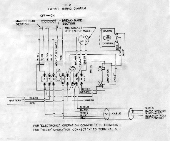
TU-KIT
INSTALLATION INSTRUCTIONS FOR AMPLIFIER IN UG-8 STAND
NOTE: READ INSTRUCTIONS CAREFULLY BEFORE STARTING MODIFICATION.
As each operation is performed check it off as "completed".
Unpack the TU-Kit and you will have:
1 Bracket assembly with battery clip and volume control. (Handle volume
control with care so as not to scratch the carbon track.)
1 Amplifier assembly
1 Battery
1 Battery connector
1 Red jumper lead
1 Screw
1 Set of instructions
1. Remove microphone from stand - set aside in safe place.
2. Remove bottom plate by removing three screws in base. Save the bottom
plate and screws.
3. Cut out and discard the GREEN jumper lead from terminal 3 to terminal 8.
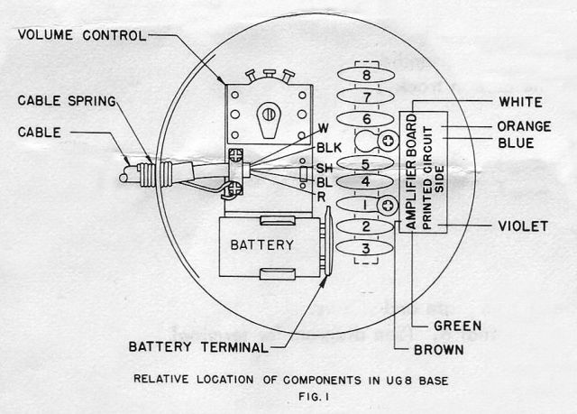
(See diagram for terminal numbers. (Fig. 2)
4. Cut out and discard the bare jumper wire between terminals 1 and 4.
5. Remove the cable clamp and cable clamp screws.
6. Locate the bracket assembly on the cable clamp boss under the table wires
(Fig. 1). See the illustration for location. Replace the cable, cable spring
and cable clamp. Secure the assembly on cable spring side with screw
supplied. Secure other side of cable clamp with one of the screws previously
removed.
7. Remove the terminal strip screws.
8. Locate the amplifier board (component side toward base) under terminal
strip lugs as illustrated. Replace the terminal strip screws and tighten.
(Fig. 1)
9. Terminal 3 - Solder GREEN amplifier lead.
10. Terminal 2 - Solder BROWN amplifier lead.
11. Terminal 4 -
(a) Unsolder WHITE/RED and WHITE/GREEN - push aside.
(b) Solder to terminal 4:
1. VIOLET amplifier lead
2. One end of RED jumper lead supplied
3. RED battery connector lead
12. Solder other end of RED jumper lead to volume control terminal as
illustrated. (Fig. 2)
13. Solder BLUE and ORANGE amplifier leads to volume control terminals as
illustrated. (Fig. 2)
14. Terminal 7 -
1. Unsolder the BLACK cable lead - push aside.
2. Solder the BLACK battery connector lead.
15. Terminal 1 -
1. Solder the WHITE/GREEN lead of step 11.
2. Solder the BLACK cable lead of step 14.
16. Terminal 8 -
Solder the WHITE amplifier lead.
17. Decide whether "Electronic" or "Relay" type operation is desired. This
determines where WHITE/RED lead of step 11 is attached.
For "Electronic" operation solder WHITE/RED to terminal 1.
For "Relay" operation solder WHITE/RED to terminal 6.
18. Snap the battery connector on battery and push the battery into battery
clip.
19. Align the bottom plate template on the felt side of bottom plate with
screw holes as marked. Locate and drill the 1/2 inch diameter hole through
the plate, (Fig. 3), if it is not already drilled as supplied by the
factory.
20. Position the bottom plate with drilled hole over volume control shaft
and secure with screws previously removed.
21. Turn volume control (with screw driver) counter clockwise to zero.
Replace microphone on UG-8 stand. Plug cable into transmitter.
22. Activate the transmitter by means of the actuating bar. Adjust volume
control with a screw driver to desired modulation level.
23. DO NOT EXCEED 100% MODULATION LEVEL. In addition to inviting a FCC
violation notice there is a very real possibility of damage to the audio
stages of the transmitter due to excessive audio. In the event it is
difficult to adjust the volume control low enough, it is suggested a 470 ohm
1/4 watt resistor be soldered from WHITE cable lead to ground. at either end
of the cable. (Terminal 8 to terminal 1 in the UG-8 stand base). Generally,
once adjusted the volume control will not need resetting during equivalent
operating conditions. The full modulation level capability of the amplifier
will seldom be required, except under unusual conditions. If you find it
necessary to use most of the amplifier gain, you should check to be certain
the gain is really needed.
24. Caution must be used on sets on which the outer housing is not both DC
and RF ground. Touching a metal microphone case to the housing may result in
damage to the set. In isolated cases RF pickup may cause improper
performance. In case of this type of trouble, please get in touch with the
factory for instruction.
Special Instruction Notes
1. The combination of these amplifiers with high level microphones may
result in critical gain setting. A "L" pad comprising two resistors results
in much less critical adjustment.
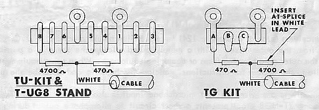
Insert 4700 ohms in series with the WHITE cable lead. Shunt 470 ohms from
WHITE cable lead to ground.
2. When wiring microphone cables and plugs to equipment, the color codes for
the cable and for the equipment are not necessarily the same. Be careful to
connect wires to the correct terminals.
3. Occasionally RF feedback presents problems. The solution is basically
good installation.
-
a. Antenna Feed line standing wave ratio must be low.
-
b. Good grounding eliminates a "hot" transmitter chassis condition which can couple RF into unwanted places. On base stations multiple grounds with different length line to each ground is good practice .
-
c. In stubborn cases it may be necessary to alter microphone cable length to a non-resonant length. A coil cord in lieu of a straight cable can be a solution.
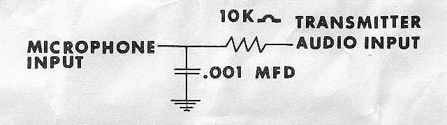
-
d. In extreme cases it has been found that installation of an RF filter in the transmitter at the audio input eliminates RF to audio input stage. This filter comprises a 10K ohm resistor in series and a .001 mfd. capacitor from the microphone input to ground.
4. Some transceivers (such as Messenger 124) have the microphone ground at a
DC potential differing from the outer case. With a metal housed microphone
there is a possibility of shorts to the outer case blowing fuses or damaging
equipment. When using equipment of this type, write to the factory for
instructions. Enclose a schematic and describe the problem.
5. Some transceivers are wired so that microphone input is also receiver
audio. The microphone preamp (T-UG8 etc.) presents a short circuit to
microphone output during receive mode.
If, when the microphone preamp is connected to the transceiver, receiver
output drops to zero, cut the WHITE cable lead at the terminal inside the
microphone base. Receiver volume will go to normal. Install a ~ watt
composition resistor in series with the WHITE lead where it was cut. Try
several values to determine the smallest value resistor that can be inserted
without appreciable effect to receiver performance. Install this resistor
permanently.
6. On initial setup it is a good practice to turn gain completely down.
After turning on the transmitter, slowly turn the gain up until desired
modulation level is reached. This procedure aids in getting gain properly
set without going through periods of excessive distortion and
over-modulation.
TU-Kit Wiring Diagram