This circuit measures short duration
events ranging from 10µs to 655ms, in 10µs increments. It
has two logic-level (TTL) inputs that can be used to measure the high
or low time of a pulse,
or the time difference between two pulses.
Applications include measuring the execution time of a
microcontroller program, the time difference between output signals in
a circuit, or the changeover time in switches & relays. It is
particularly useful for measuring one-off events that can be difficult
to catch on a scope.
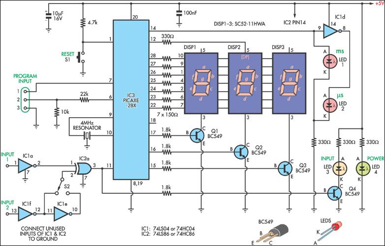
The circuit uses three 7-segment common-cathode LED displays for the
readout. Two individual LEDs indicate whether the reading is in
microseconds or milliseconds, with the software
automatically selecting
the correct range. LED4 is the
Power ON indicator.
The circuit requires +5V at approx. 25mA in standby and 100mA with all 18 segments turned ON. In many cases, this can be sourced from the circuit under test.
A PICAXE microcontroller measures the length of high-going pulses
applied to pin 11. This pin is driven by the output of a 74LS86 XOR
gate (IC2a). Two 74LS04 inverters (IC1a & IC1f)
feed the XOR gate
and act as buffers for the two inputs. Additionally, one of the inputs
had a second inverter that can be switched in or out of the circuit
with S2.
Timing starts as soon as the signals applied to the two inputs
differ, generating a high-going pulse on pin 11 of the micro. When both
inputs again match, timing stops and the pulse length is displayed.
Timing is also terminated if the pulse width exceeds the maximum
measurement period (0.65s).
When only one input is required, the signal should be applied to
input 2 and input 1 grounded. LED3 indicates the state of the signal on
the PICAXE input. Prior to the measurement, it should be OFF.
If not,
toggle switch S2 to invert the signal. The switch therefore allows the
measurement of both high and low-going pulses.
Referring now to the program listing, the PICAXE pulsin
command is used to measure the pulse high time, which is stored in the
variable word w5. This part of the program loops until a value
greater
than zero is detected.
Measurement is in 10µs steps, so when the number 1 is
returned, it corresponds to a time of 10µs. Be aware that a
43µs pulse will be read as a 4 and displayed as 40µs. This
loss of precision only
occurs in measurements under 1ms. Measurements
over 1ms are correct.
When a pulse is detected, w5 is tested to see if it is
greater than 99 (990µs). If not, simple division splits the first
2 digits into b1 and b2. The "µs" indicator
(LED2) is then turned ON by setting pin 13
(portc 2) low.
If the value is greater than 99, the software jumps to the "ms:"
section. First, the "ms" indicator (LED1)
is turned ON by setting pin
13 (portc 2) high. Next, a check is made to see if w5 is less
than 99ms.
If so, there must be a decimal place, so the decimal point
is turned ON (portc 3). Division of the returned value occurs, with the
results in b1, b2 and b3.
If w5 is greater that 99ms, then the "high_ms:" routine is
executed. The value in w5 is divided by 1000, placed in b0,
and
the
first two digits divided into b1 and b2. To get
the third digit, b0 is multiplied
by 1000 and placed in w4.
Again, the results are returned in variables b1-b3.
Finally, the results from the "decode:", "ms:" or "high_ms:"
sections are displayed on the readout by the "display:" routine. This
part of the program loops back on itself, so that the last measurement
is held
on the display until the reset switch (S1)
is pressed.
Seven of the PICAXE-18X’s dedicated output pins (out1 - out7) are
used to drive the segments in each of the displays via 150Ω
current-limiting resistors. The value for each digit is stored in the
variables
b1, b2 & b3, as described above.
Using the lookup command, the program converts these values into a binary pattern needed to illuminate the correct segments. The result is then written to the output port using the pins command.
As the anode pins of all three displays share the same seven output
lines, a multiplexing technique is used to sequentially enable each
display for 3-5ms at a time. This is achieved in the circuit by turning
ON
transistors Q1, Q2 & Q3 in turn, grounding the common-cathode
pins of the displays. Three portc output pins drive the transistors via
1.8kΩ biasing resistors.
A secondary use for this circuit and software is as the basis for
any project where 7-segment readouts need to be driven by a PICAXE.
This is achieved simply by omitting the input circuit and indicator
LEDs.
Also, delete the program lines prior to the "display:" routine.
In its present form, the "display:" routine will drive three
7-segment displays, though a fourth is easily added.
Download the code here: timer-short.bas
Copyright © 2008-2014 Ted J. Mieske
All Rights Reserved.