Here
are
some
notes
that
may
keep
you
from
'frying'
a
PICAXE!
1. NEVER supply
a voltage over +5.5VDC, not
even +5.6VDC, to a PICAXE!!
The closest you can get, is to use
rechargeable-- Four AAs, output
+4.8VDC,
whereas Four standard AAs will output
+5.2VDC
or
greater.
If
a
power
supply
is used, it's output should be set to +5.0VDC
via
Voltage
Regulator.
2. Manual #1 on page
#8 shows the typical setup
between the PICAXE and the,
(USB or Serial cable) that plugs into a 3.5mm
Jack
mounted on your project board.
Their are two
resistors, 22k & 10k that make up the network going to the
Serial-In
Leg of the PICAXE.
NOTE:AXE026
is
the
Serial
Cable. It doesn't always work due to the levels com-
ing
in
and
out
of
the
Serial
Port!
Sparkfun
carries a
board that will fix this
problem. The newer Laptops seem to have this problem the most.
NOTE:
People
overseas
tend
to
do
the opposite of us in the USA. A 3-pin
Stereo
3.5mm
Jack
in
general,
has
the
larger
band
nearest
to
the
connector/cable
is
always
Ground.
But
Europeans,
(and
the
company
that
make
the AXE027
USB
cable),
have
the
Tip,
(at
the
end
of
the
connector)
as
ground.
Go
figure!
Isn't
it
FUN
to
compare
notes--
YAWN?
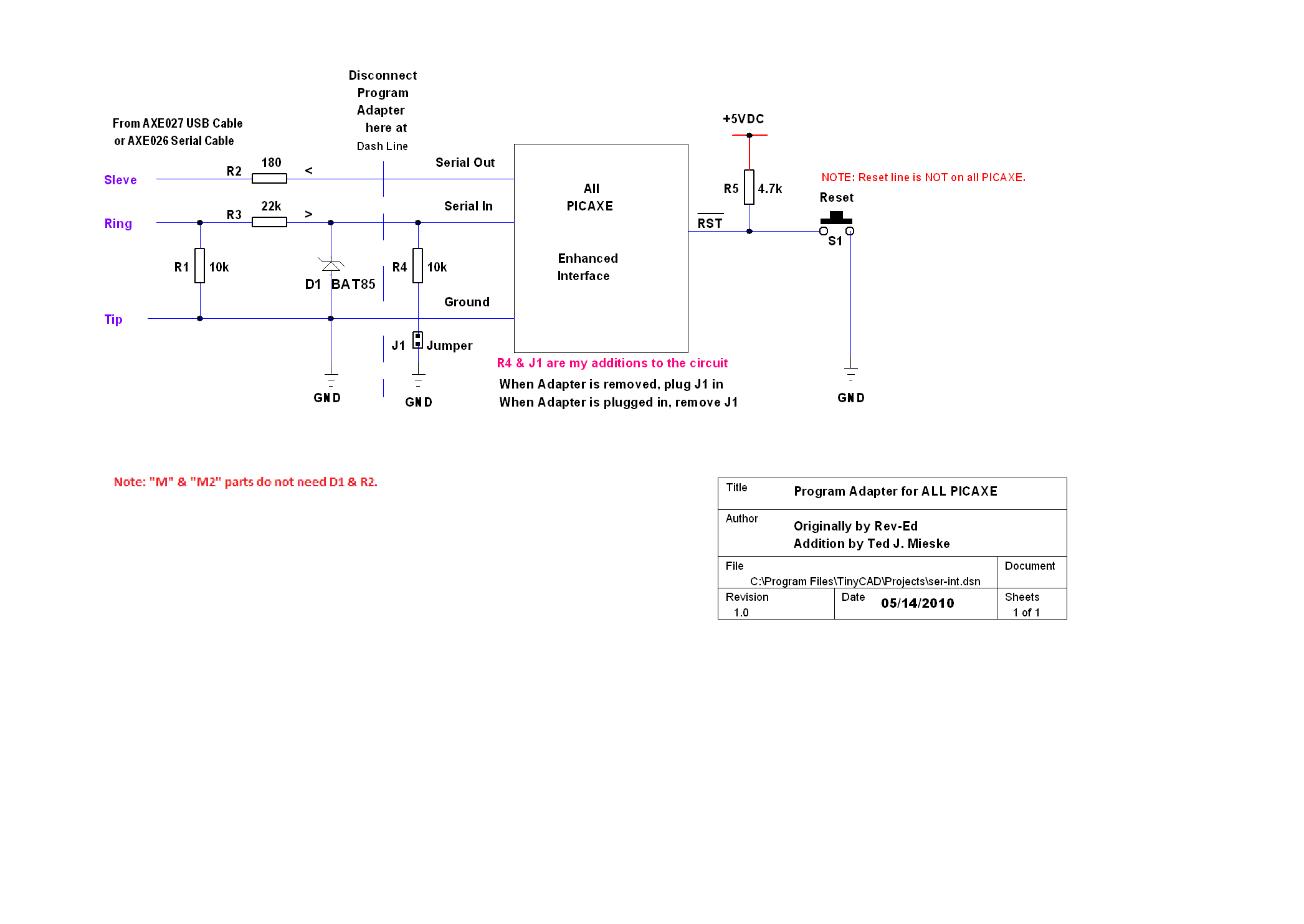
The following
is a screen shot of my enhanced version for the Programmer / interface. My
circuit
leaves
out
four
parts
for
each
project
you
need to program. You
will only need
one resistor and a shunt-jumper after the Programing Cable is removed.
3.
In
manual
#1,
see
diagram
on
page
#45
for
an
advanced setup for programing
a
PICAXE. This is much more stable then
the circuit on page #8. I will keep this
page up to date; the 3 manual's have also been
updated. The new 18M2, 14M2,
20M2 and the 08M2 chip's has been released and have
some new
commands.
Manual #1 & #2 have been updated, again to
reflect these changes: July 2011.
4.
If
you
remove
the
program
cable
from
your
project,
make
sure,
(if
you
have
a
PICAXE that has a "Reset" line), to place a
4.7k resistor between +5VDC and
the Reset line. Leaving it "floating"
may give unknown results. If you don't
have a 4.7k Resistor, you may substitute with
a Resistor value up to 10k. This
is not
true for the 08M & 14M. There
is no Reset line. Power-OFF, wait a
couple of seconds, turn it back ON, this
will put you back in business. You
can always re-download the code as well.
If it still does not reset the 08M
or 14M, then pull the power cable to your
project, start the download, then
apply power once again to your project. The
has always worked for me.
5. Please note that the 28X2 and the 40X2 Power Legs handle any
voltage
between +2.1VDC and 5.5VDC. This is also
true of the M2
class of PICAXE.
Here
is
a
Quick
list
of
what
you
will
find
in
Manual
#3
Page 8, 12 - Using IRF5xx or IRL5xx components to drive a
Motor.
Page 8, 14 - Interfacing to a Relay.
Page 9 - Driving LEDs.
Page 10 - Driving a Light Bulb or Buzzer.
Page 11 - Piezo Sounder or 40Ω Speaker. Caveat: A 10uF
Electrolytic
Capacitor
connects
to
a
Speaker.
The
"+"
side
of
the Capaci-
tor goes to the
OUT PIN of the PICAXE. The negative side
of
the
Capacitor
goes to the "+" side of the Speaker, and the
"-"
side
of
the Speaker goes to Ground.
Page 12 - A Solar Motor, (or a Toy Motor in general), should have
a
.22uF
Capacitor
across
the
solder
lugs
of
the
Motor.
Page 13, 18 - Using an L293D, (or L393), are used to drive 2-motor
circuits.
They
take
care
of
the
higher
current
that
these
motor's
demand.
(Info
on
the
L298 should be here also.)
Page 15-16 - Working with Unipolar Stepper Motors.
Page 17, 18 - Working with Bipolar Stepper Motors.
Page 19 - Interfacing with Servo Motors. Note the Capcitor &
Resistor.
Page 29 - Using LDRs, (Light Dependant Resistors.)
Page 30 - How to wire a Thermistor.
Page 31-42 - Working with LCD Displays.
Page 43-46 - Interfacing to a PC, (Computer), via Serial connection.
Page 44 - MAX232 Serial Interfacing.
-------------
For some reason, the following are missing in
Manual #3 v4.4 -------------
Page 45 - Enhanced Serial Circuit. (see my schematic above for details).
This
is
all
that is needed to program a PICAXE.
Page 49 - Hard-Reset
Page 69 - Digital In, Digital Out, Analogue.
Page 76 - Making Sounds: Buzzer, Piezo, Speaker.
Page 77 - Switches.
Page 78 - LDR (Light Depandant Resistor).
Page 79 - DS18B20 Temperature reading device. Use a pull-up
4.7k
resistor
between
the output of the DS18B20 and VDC.
Page 83 - Using Interrupts
Page 105 - FAQ's
----- NOTE:
Code
is
mixed
within
the
circuit's...some
quite generously.
NEW
additions:
I2C is a 2-PIN connection between the PICAXE and the I2C device(s).
Both lines should have a 4.7K resistor from the SDA and SCL lines
and connected to VDC at the other end of the resistor's. Only need this
ONCE on each LEG, no matter how many I2C devices are connected.
See page #6 of the AXE033.PDF manual.
1-Wire devices-- there should be a 4.7k resistor between DQ LEG and
VDC.
Here is a breakdown on the LEG/PIN
assignments of an 08M.
This will be true for any PICAXE, but will have other LEG/PIN
assignments.
So a LEG is the physical Leg on the device; where as
the PIN has the assignment for what ever feature it can handle on
the LEG. Below is an explanation of how this is done with an 08M.
Ok, let's look at the facts--we will use the 08M on the
LEGs/PINs assignment.
1. Currently there are I/O lines
that do not
necessarily match the same physical LEG to the same use of
that device. (i.e. On an 08M Physical
LEG 3, is an IN/OUT PIN 4).
2. According to Manual #1, pg 27
08M-- Physical
LEG2
is
STRICTLY
Serial
IN It should
also be hooked-up to the 22k & 10k according the the diagram on that
page. 3. Physical LEG 4 is Strictly an IN PIN 3 (i.e. use a switch to trigger
something.)
4. Physical LEG 7 serves two purposes. OUT 0 and SERIAL OUT (output
ONLY) Serial OUT is
sent back to the PC, and with the 'debug command', you can watch your
Computer Monitor to see what is happening. This PIN also is used by the
'Program Editor' to let it know that the PICAXE programmed correctly. (Also note on pg #45 that 180Ω resistor is added. Good practice.) That's
your
first
OUTPUT
PIN
0
5. LEG 6 is IN/OUT PIN 1 plus it can be
used for ADC circuits.
6. LEG 5 is IN/OUT PIN 2
7. LEG 4 is INPUT PIN 3
ONLY!
8. LEG 3 is IN/OUT PIN 4
-------
So let's recap: LEGS 7, 6, 5, 3 are OUTPUTS LEGS 4,6, 5, 3 are INPUTS
Notice that LEG 6, 5, 3 are
the TRUE I/O PINS.
Bypass Caps are NOT an option...put them IN even if running on Batteries. .1uF is a good practice and it won't
cost but pennies to do so! Might as well take care of noise
and one less thing to be concerned about.
----- One more item, when the Programming
Cable is NOT plugged
in, take a 10k resistor
from LEG 2 (Serial IN) to J1 then
ground.) This has cleared up more then
once, spurious problems hardware people have found.